How to Make a Wooden Garden Chair with Your Own Hands
How to Make a Wooden Garden Chair with Your Own Hands
Share on Twitter
Post to Blog
Email
Share on Twitter
Post to Blog
Such a portable wooden garden chair with small wheels is made using a circular saw with a 20 mm thick disc, which is used to cut out wood for joints in half-wood and tongues (photo 1), as well as grooves (photo 2). Holes for attaching chair parts are drilled with a combination drill (photo 3), which allows you to get a countersunk hole for screws immediately.
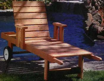
Garden Chair Made by Yourself
Handles A of the garden chair (see parts list and figure 1) are cut out with a bandsaw according to a template glued onto the workpiece (photo 4). The same method is used for making L-shaped crossbar strips of the garden chair – a template is glued to them with sticky tape (photo 5), and then the edges are shaped according to it. The crossbar M of the crossbar is attached to the strips with screws 42 mm long, placing the strips on a bench so that their tips lie flat against the surface and are flush with the crossbar. Auxiliary holes are drilled in the crossbar through the holes in the strips and they are fastened (photo 6).
In the back panel N, in the middle of the upper rib, a hand hole is cut out to lift the backrest when it is in the lower position. A circle is drawn with a compass at R=125 mm, with a radius segment of g=32 mm (photo 7), and the hand hole is cut out with a bandsaw. At a distance of 20 mm from the lower rib of the back panel, auxiliary holes with wooden plugs (photo 8) are made at equal intervals using a combination drill.
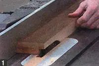 Cutting out tongues, side tongues...
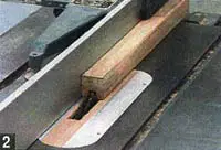 ...and grooves with a 20 mm thick blade.
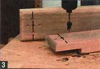 Using a combination drill to make holes for screws.
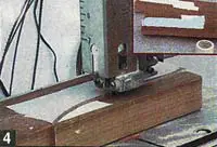 Cutting handles and...
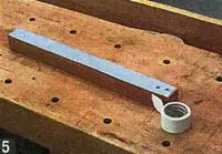 ...crossbar strips according to a template.
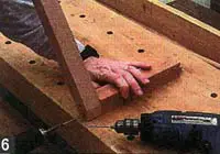 Assembling crossbar strips and crossbar.
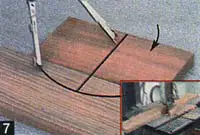 Marking the hand hole in the back panel.
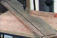 Screw placement in the back panel.

Figure 1. Garden Chair Parts
The front ribs G of the armrests and all ribs of the armrests F are rounded with a router at R=12 mm. Each armrest support is attached to the side panel with screws 42 mm long.
In both limiting blocks K of the seat, auxiliary holes (photo 9) are drilled at equal intervals. After that, the limiting blocks are attached to the central crossbar J of the seat with screws 42 mm long.
According to figure 2, two rear legs E are attached to the central support of the seat with screws 42 mm long and to the inner ribs of side panels A with screws 64 mm long. Then, the front legs D are attached to the inner ribs of the side panels with screws 64 mm long and the front leg crossbar C is attached to the legs with screws 42 mm long.
The W Ø12 mm axis made of stainless steel is required for rotating the backrest. It is passed (photo 10) through both supports H of the backrest, installed at a distance of 75 mm from the side panels.
A Side Panels - Handles 2 Pine 38x89x2133
B Seat Strips 18 - 20x89x558
C Front Leg Crossbars 1 - 38x89x482
D Front Legs 2 - 38x89x406
E Rear Legs 2 - 38x139x343
F Armrests 2 - 38x89x305
G Armrest Supports 4 - 38x89x305
H Backrest Supports 2 - 38x70x698
I Backrest Strips 7 - 20x89x520
J Central Seat Crossbar 1 - 38x139x482
K Limiting Blocks of Seat 2 - 38x38x482
L Crossbar Strips 2 - 38x38x432
M Crossbar of Crossbar 1 - 38x38x222
N Back Panel 1 - 20x89x596
O Axis Mounting Plate 1 - 38x38x482
Additional materials for folding crossbar: M10x100 bolts with nuts (2 pcs.), washers Ø25 (4 pcs.), washers Ø38 (2 pcs.), Grovers washers Ø17 (2 pcs.) and axis washers Ø38 (4 pcs.); threaded rod M12×900 with nuts (1 set); stainless steel axis W Ø12×500; wood screws for outdoor use 42 and 64 mm long; double-sided sticky tape; wooden plugs; wheels Ø250 mm (2 pcs.).
Strips B in the front part of the garden chair, starting from the handles, are arranged on the side panels with 12 mm thick spacers and fastened with screws 42 mm long.
Each backrest strip is pressed against its supports flush with their ends. The backrest supports are lifted up and the gap between the side panels and the strip is checked. Strips are fastened to the side panels with a 12 mm gap between them using screws 42 mm long, and the crossbar is attached to the backrest supports with M10×100 bolts with nuts, washers Ø25 and 38 mm, and Grovers washers, passed through Ø10 mm holes (photo 11).
According to figure 2, the placement of armrest supports is marked and they are attached in place with screws 64 mm long: first the one closest to the backrest, and then another one is placed 89 mm away and fastened.
The rear crossbar P of the seat is attached to the side panels with two screws 64 mm long and checked that its lower rib is flush with the lower rib of the side panels, and the side ribs of the crossbar are flush with the ends of the side panels.
The axis is inserted through the holes and the axis mounting plate is attached with screws 64 mm long above it. Then this axis is inserted through the holes in the rear legs and a Ø38 mm washer is slipped between the rear leg and the wheel. Another washer is slipped outside the wheel. The nuts are tightened (photo 12), the final length of the axis is determined and it is cut off.
Finally, the garden chair is coated with water-resistant varnish.
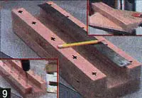 Marking holes in the limiting blocks of the seat.
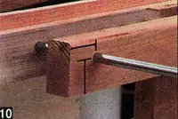 Backrest supports.
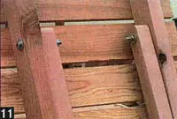 Assembling the crossbar.
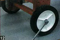 Assembling the wheels.
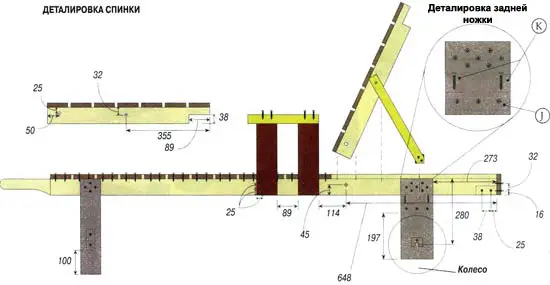
Figure 2. Side View of the Garden Chair
In the end, you get a wonderful, comfortable and cozy garden chair made by yourself. Good luck!
Garden Chair Made by Yourself
Handles A of the garden chair (see parts list and figure 1) are cut out with a bandsaw according to a template glued onto the workpiece (photo 4). The same method is used for making L-shaped crossbar strips of the garden chair – a template is glued to them with sticky tape (photo 5), and then the edges are shaped according to it. The crossbar M of the crossbar is attached to the strips with screws 42 mm long, placing the strips on a bench so that their tips lie flat against the surface and are flush with the crossbar. Auxiliary holes are drilled in the crossbar through the holes in the strips and they are fastened (photo 6).
In the back panel N, in the middle of the upper rib, a hand hole is cut out to lift the backrest when it is in the lower position. A circle is drawn with a compass at R=125 mm, with a radius segment of g=32 mm (photo 7), and the hand hole is cut out with a bandsaw. At a distance of 20 mm from the lower rib of the back panel, auxiliary holes with wooden plugs (photo 8) are made at equal intervals using a combination drill.
Cutting out tongues, side tongues......and grooves with a 20 mm thick blade.Using a combination drill to make holes for screws.Cutting handles and......crossbar strips according to a template.Assembling crossbar strips and crossbar.Marking the hand hole in the back panel.Screw placement in the back panel.Figure 1. Garden Chair Parts
The front ribs G of the armrests and all ribs of the armrests F are rounded with a router at R=12 mm. Each armrest support is attached to the side panel with screws 42 mm long.
In both limiting blocks K of the seat, auxiliary holes (photo 9) are drilled at equal intervals. After that, the limiting blocks are attached to the central crossbar J of the seat with screws 42 mm long.
According to figure 2, two rear legs E are attached to the central support of the seat with screws 42 mm long and to the inner ribs of side panels A with screws 64 mm long. Then, the front legs D are attached to the inner ribs of the side panels with screws 64 mm long and the front leg crossbar C is attached to the legs with screws 42 mm long.
The W Ø12 mm axis made of stainless steel is required for rotating the backrest. It is passed (photo 10) through both supports H of the backrest, installed at a distance of 75 mm from the side panels.
Parts and Materials List
Part No.
Part Name
Quantity
Material
Dimensions, mm
A Side Panels - Handles 2 Pine 38x89x2133
B Seat Strips 18 - 20x89x558
C Front Leg Crossbars 1 - 38x89x482
D Front Legs 2 - 38x89x406
E Rear Legs 2 - 38x139x343
F Armrests 2 - 38x89x305
G Armrest Supports 4 - 38x89x305
H Backrest Supports 2 - 38x70x698
I Backrest Strips 7 - 20x89x520
J Central Seat Crossbar 1 - 38x139x482
K Limiting Blocks of Seat 2 - 38x38x482
L Crossbar Strips 2 - 38x38x432
M Crossbar of Crossbar 1 - 38x38x222
N Back Panel 1 - 20x89x596
O Axis Mounting Plate 1 - 38x38x482
Additional materials for folding crossbar: M10x100 bolts with nuts (2 pcs.), washers Ø25 (4 pcs.), washers Ø38 (2 pcs.), Grovers washers Ø17 (2 pcs.) and axis washers Ø38 (4 pcs.); threaded rod M12×900 with nuts (1 set); stainless steel axis W Ø12×500; wood screws for outdoor use 42 and 64 mm long; double-sided sticky tape; wooden plugs; wheels Ø250 mm (2 pcs.).
Strips B in the front part of the garden chair, starting from the handles, are arranged on the side panels with 12 mm thick spacers and fastened with screws 42 mm long.
Each backrest strip is pressed against its supports flush with their ends. The backrest supports are lifted up and the gap between the side panels and the strip is checked. Strips are fastened to the side panels with a 12 mm gap between them using screws 42 mm long, and the crossbar is attached to the backrest supports with M10×100 bolts with nuts, washers Ø25 and 38 mm, and Grovers washers, passed through Ø10 mm holes (photo 11).
According to figure 2, the placement of armrest supports is marked and they are attached in place with screws 64 mm long: first the one closest to the backrest, and then another one is placed 89 mm away and fastened.
The rear crossbar P of the seat is attached to the side panels with two screws 64 mm long and checked that its lower rib is flush with the lower rib of the side panels, and the side ribs of the crossbar are flush with the ends of the side panels.
The axis is inserted through the holes and the axis mounting plate is attached with screws 64 mm long above it. Then this axis is inserted through the holes in the rear legs and a Ø38 mm washer is slipped between the rear leg and the wheel. Another washer is slipped outside the wheel. The nuts are tightened (photo 12), the final length of the axis is determined and it is cut off.
Finally, the garden chair is coated with water-resistant varnish.
Marking holes in the limiting blocks of the seat.Backrest supports.Assembling the crossbar.Assembling the wheels.Figure 2. Side View of the Garden Chair
In the end, you get a wonderful, comfortable and cozy garden chair made by yourself. Good luck!